Concrete Reinforcement Detailing in Revit Structure: A Practical Guide
Reinforcement detailing has long been a source of site delays, manual coordination, missed bars, clashes, inconsistent schedules, and the pain of rework when late changes hit. The industry is moving beyond 2D into a coordinated 3D/BIM environment, and Revit Structure is at the centre of that shift.
In this post, we summarise a live demonstration from Civil Survey Solutions, presented by Structural Application Engineer Asif Khan and hosted by Ben Hipsley, showing how to model, coordinate, and document concrete reinforcement in Revit efficiently and accurately.
Why move rebar to Revit?
Precision: Bars are placed exactly where they’ll be installed, hosted to the concrete elements (slabs, beams, cores, columns).
Automation: Tags, bar marks, and schedules are generated directly from the model and update with design changes.
Coordination: Run early clash checks against adjacent disciplines to prevent site surprises.
Change management: When geometry or rebar changes, all related views and schedules update together.
Communication: 3D visualisation helps site teams understand intent at a glance.
Core workflow, step by step
1) Establish covers (by element or face)
Set global covers first, then refine by faces that contact soil or need increased protection (e.g., 75 mm external, 35 mm internal). The cover visualisation helps confirm compliance before placing steel.
2) Place and propagate rebar
- Use standard shapes (e.g., straight, U, L, stirrups) and assign size, count/spacing, and hooks.
- Work in section/detail views for controlled placement; turn on “view unobscured” when reviewing in 3D.
After placing a well-configured set, propagate it to similar hosts to eliminate repetitive work.
3) Model longitudinal bars and hooks
- Place straight bars, add hooks, then adjust lengths with grips or numeric constraints.
- Mirror or copy as needed, then fine-tune clearances to meet code cover and anchorage requirements.
4) Create crank bars and custom shapes
- Convert straight bars into cranked or custom shapes via Edit Sketch, using simple CAD-like line and trim tools.
- Keep shape rules consistent for reliable scheduling.
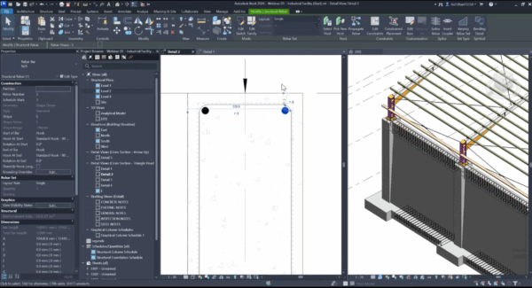
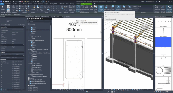
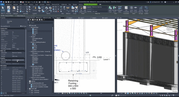
5) Footings, retaining walls, and tapered elements
- For footings: use L/double-L sets, fix orientation with the spacebar, and adjust legs to satisfy development.
- For retaining walls: place face-specific L-bars, offset pairs to avoid overlap, and use variable spacing where shear demand changes.
- For tapered/non-uniform geometry: split reinforcement into zones where slopes change, then use varying rebar sets. This maintains stability and makes intent clear to fabricators.
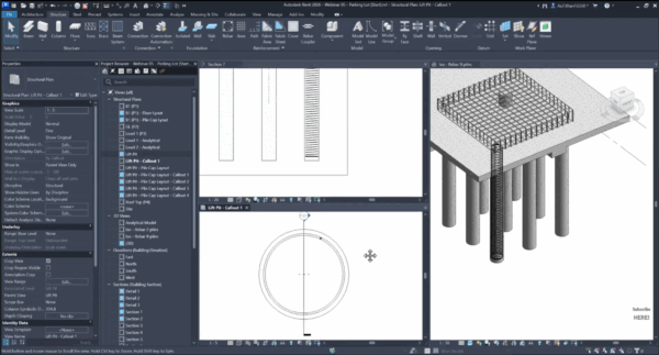
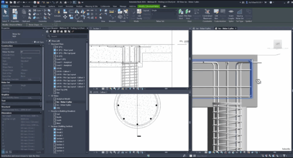
6) Piles and pile caps
- Apply spiral reinforcement to piles and set bottom/top covers appropriately.
- Add L-shaped longitudinal bars; use radial arrays to distribute evenly. If arrays need local tweaks, break the group to edit specific bars near pile-cap edges.
Detailing and documentation
Clear, consistent tagging
- Multi-rebar tags in sections and plans report bar size, count/spacing, and mark directly from the set.
- Use custom tags (e.g., CSS “open-dot” section tags) for clean callouts that match your office standard.
Bending details and bar marks
- Add bending details to sectioned or selected bars so fabricators can read shape codes and lengths without ambiguity.
- Bar marks and schedules update automatically; filter schedules by mark to verify nothing is missed (selecting schedule rows highlights bars in model views).
Sheet production
- Place long sections, cross-sections, and plan details on sheets with consistent view titles and legends (e.g., dark linework for top bars, dashed/grey for bottom bars).
- Use colour accents or dimensions sparingly to show critical transition points (e.g., stirrup spacing change zones).
Tips & tricks from the demo
- Set covers first. You can change them later, but starting right avoids rework.
- Use propagation. Model once, then reuse across similar beams/walls/footings.
- Mind development length. Adjust hooks/leg lengths with numeric constraints for repeatability.
- Zone complex shapes. Revit prefers clean slope boundaries, split reinforcement where geometry changes.
- Array with intent. Radial arrays speed pile reinforcement; break grouping only when local edits are necessary.
- Present one bar when clarity matters. For congested plans, temporarily show a single representative bar with full annotation.
The bottom line
Rebar in Revit isn’t just “3D for looks”, it’s a coordinated, data-rich workflow that reduces errors, accelerates revisions, and produces fabrication-ready documentation. With covers set correctly, smart use of standard shapes and propagation, and disciplined tagging/scheduling, teams can move from reactive rework to proactive delivery.
If you’d like help setting up standards, tags, and templates, or want a guided session on piles, retaining walls, or varying rebar sets, Civil Survey Solutions can get you there faster.
About The Author

We are the leading provider of civil engineering and survey software solutions and services in Australia.