Steel Connections in Revit Structure: From Parametric Modelling to Rapid Documentation
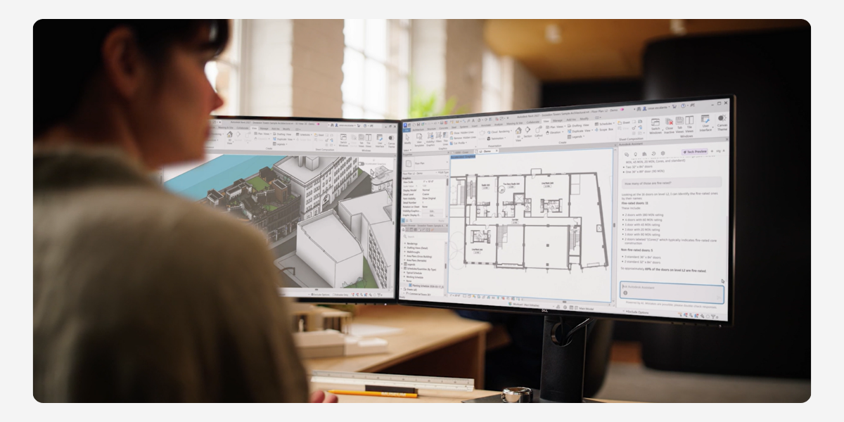
In the fourth session of our Revit Structure webinar series, we explored one of the most practical wins for structural teams: modelling steel connections directly in 3D. If you’ve ever had a connection detail trigger RFIs or site delays, you’ll know why this matters. Revit’s out-of-the-box (and customisable) connections, paired with parametric control and automatic documentation, can dramatically reduce rework and improve coordination.
Why model steel connections in 3D?
Designing connections in 2D often means translating complex geometry into linework, duplicating details, and manually updating drawings when designs change. A 3D, data-rich approach in Revit addresses those pain points:
- Single source of truth: Update a connection once and the change flows to all associated plans, sections, details, and schedules.
- Real-time coordination: Use interference checks to catch clashes with MEP, walls, and adjacent structures before they become onsite problems.
- Constructability built in: Visualise weld access, bolt clearances and plate edge distances in context—no guesswork.
- Rules & standards enforced: Parameters (e.g., plate edge distances vs bolt sizes) maintain compliance as sizes or layouts change.
- BIM-ready delivery: With more projects mandating BIM/digital engineering, a 3D connections workflow keeps your practice competitive.
A typical Revit workflow for steel connections
- Model the primary frame (columns, beams, rafters, bracing).
- Load connection libraries (standard + any firm-specific/custom types).
- Place and configure connections using type parameters and instance controls.
- Propagate connections to similar conditions automatically.
- Run clash detection and resolve before documentation.
- Produce drawings and exports (fabrication/IFC) from the coordinated model.
In the live demo, we focused on placing, editing, and propagating connections, then moving straight into drawing production, no extra linework required.
What we demonstrated (with practical examples)

- Base plates
- Control plate thickness, projections, anchor patterns, washer/shim/levelling plates, and web/flange stiffeners.
- Propagate to identical column conditions to avoid repetitive placement.
- Use type duplication for different member sizes (e.g., 310 UB vs 410 UB) to keep variations clean and manageable.

- Rafter apex & knee haunches
- Assign primaries/secondaries correctly (Revit’s centreline graphics make this obvious).
- Duplicate types for internal vs external frames (e.g., different haunch lengths).

- Beam–column connections
-
- End-plate, double-sided end-plate with safety bolts, clip-angles, shear plates and splices.
- Adjust bolt patterns, set-outs, and plate sizing from the Modify Parameters panel, then re-use across the model.

- Bracing connections
- Tube-to-tube nodes (two diagonals), gusset plates to columns/beams, direct bolting for back-to-back angles, and tension rod terminations.
- Swap families on the fly (e.g., triangular gusset to alternative plate scheme) and keep logic procedural—connections adapt when member sizes or alignments change.

- Large trusses & transport splits
- Use Revit truss tools to define geometry, then explode to individual members for connection detailing.
- Apply tube end-to-end or splice plates for transportable segments; colour-code segments to guide fabrication.
Documentation: fast, consistent, and live-linked
Because the details are driven by model geometry and parameters, documentation becomes largely automatic:
- Dimensions & tags pull live values (e.g., plate thickness, bolt grades, edge distances).
- A quick visibility trick: switch a view to Wireframe to snap to anchor centre lines for accurate bolt spacing.
- Change once, update everywhere: If a plate thickens from 20 mm to 25 mm or projection reduces from 100 mm to 75 mm, all tags and dimensions update immediately across your sheets.
Customising beyond out-of-the-box
Many firms keep DWG libraries of typical details. We can help build equivalent custom Revit connections with your preferred parameters, naming, and rules, so your team gets the familiarity of “house-standard” details with the power of parametric BIM.
Key takeaways
- 3D, parametric connection modelling reduces RFIs and site issues.
- Propagation and type management slash repetitive work.
- Live-linked tags and dimensions make documentation faster and safer.
- Custom libraries give you the best of both worlds: your standards, in Revit.
Continue your learning
This session is part of our ongoing Revit Structure series. Next up: Concrete reinforcement and advanced integrations for analysis and fabrication. If you’d like help building a custom connection library or want hands-on training for your team, get in touch with Civil Survey Solutions.
About The Author

We are the leading provider of civil engineering and survey software solutions and services in Australia.